Friday, August 18, 2023

Arado E 395

ARADO E.395


Outline

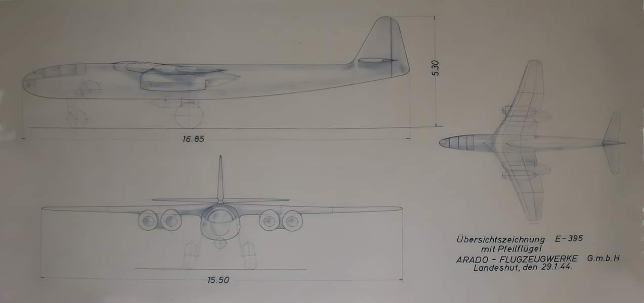
Similar in apearence to the Arado 234, the E.395 was a design proposal by Arado for the Strahlbomber competition [Hitler's 'Wonder Weapon' Bomber Projects Luftwaffe Secret Bombers of The Third Reich, by Dan Sharp]. As such, it was both longer and had a greater wing span. 

Two different and interchangeable wing design were proposed, a straight wing and a crescent version. 

The design proposal outlines two different engine configurations; with HeS 011 or Jumo 012. Drawings seem to depict a four engine configuration with HeS 011's with a total thrust of approximately 50kN. That value would be reached or exceeded with only two Jumo 012's. Leading to the conclusion that only two Jumo's were planned, despite the lack of information in primary sources to confirm that assumption. Only one drawing shows the Jumo version. But that sideview does not visualize the number of engines. 

General Data


Weight Data

Engines

Only little information is available on the Jumo 012 engines. This Jumo engine configuration is the most interesting one however. There are only a handful of aircraft designs planned to use this engine which was in it's initial planning phase. Development of the engine was continued after WW2 in Russia. 


Jumo 012A dimensions (Source http://hugojunkers.bplaced.net/junkers-jumo-012.html):


More information about the Jumo 012 in Russia can be found in old CIA reports: https://www.cia.gov/readingroom/search/site/Jumo%20012%20Development%20at%20Kuybyshev

Aircraft Layout
Overall layout of the design is assumed to be similar to the 234. A good source of information is the 234 handbook. 
Images of frame 4 and 15 are displayed below (Source: 8-234 B-2 Flugzeug Handbuch). Frame 4 also serves as the back wall of the cockpit and contains a fitting for the nose landing gear. 
The image below shows an original drawing of the E.395 (slightly enhanced/ Jumo version). 
Original sideview with Jumo 012 engines. The image has been cleaned and scaled. 

Landing Gear
Due to it's similarities with the 234, it can be assumed that many other design characteristics can be directly applied to the E-395.
The nose landing gear is moved by two hydraulic actuators and suspended with a central spring.  This spring cylinder is placed in the direct compression load path of a support rod connected with a rotational joint. If extended, this rod/spring arrangement is pushed through and rotates into coaxial alignment thereby taking up a major portion of the impact loads. 
Nose landing gear extended.
The retracted nose landing gear forms a compact arrangement. 
Nose landing gear retracted. 
Nose landing gear side view. 

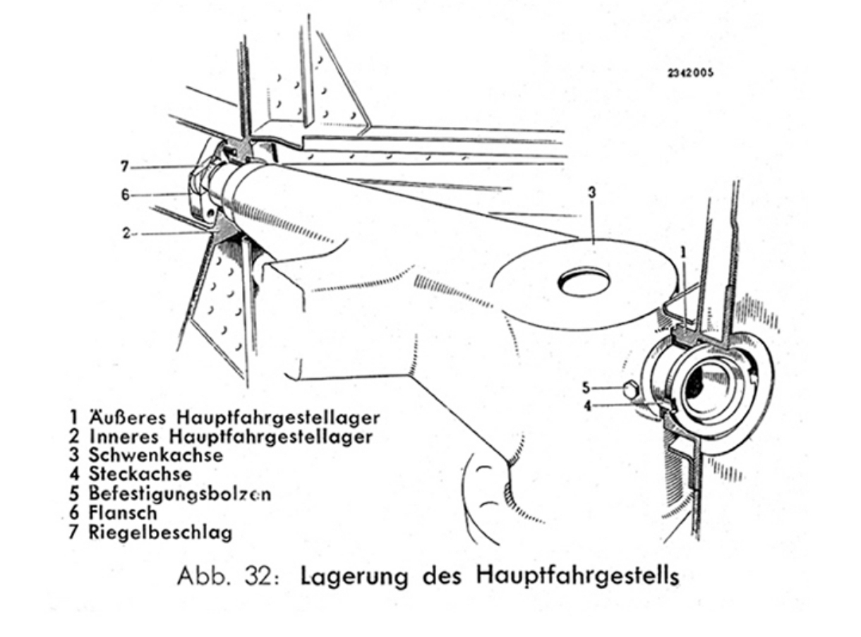
The main landing gear leg is connected to the fuselage with a swivel axis. Attached to the swivel axis is a cantilever. Hydraulic actuators use the cantilever to create a rotational moment that actuate the main landing gear leg. 

Main landing gear swivel axis.

In contrast to the Arado 234, the E.395 was planned with a two man crew. 
E.395 top view. 
E.395 side view. 

Another original drawing was found here: (https://polska-org.pl/6831343,foto.html). The drawing was apparently sold.
Data sheet from the German report, also to be found in the Lockheed report ATT 19152. 


Saturday, February 11, 2023

The EMW A-6


EMW A-6

Introducing 

From the www.nevingtonwarmuseum.com:

The A4b, manned as an aerodynamic research aircraft, the A9, as an intercontinental bomber and the A6, as a photo reconnaissance aircraft operating at great height and speed.

Actually, the military application of these scientific research programs were emphasized in order to obtain the necessary resources given the wartime circumstances.

The A6 could have been a hypersonic research aircraft, equipped with an auxiliary "Ramjet" engine, which could only be started at very high speeds.

The EMW A-6 looks definitely cool enough to justify making a model kit for it. And as far as I know, there is no 1:48 scale model kit on the market currently. 


Basic data

Purpose:                         
‘Supersonic research aircraft

Wings:                           
Metal structure and skin

Fuselage:                       
Metal structure with metal skinning covering the nosewheel, the pressurized cockpit, the methyl alcohol tank, the gasoline tank (Br-Stoff) for the turbo-ramiet engine, the under- carriage wells and the payload (instruments, cameras). Also contained in the fuselage are the tank for the liquid oxygen, the rocket motor and the combustion chamber.

Tail Section:
Metal structure with metal skinning, plus small guide vanes in the rocket nozzle. The ventral fin normally installed on the A4 and A4b could be deleted to accommodate the turbo ramjet engine.

Undercarriage:
Tricycle undercarriage

Power Plant:
One EMW rocket producing 27 500 kg of thrust and acceleration up to 6g. One turbo-ramjet engine of unknown type and performance. 

Fuel:
A-Stoff (liquid oxygen) and M-Stoff (methanol)

Wingspan:                     6.33 m
Length:                         15.75m
Height:                         4.07 m
Maximum diameter:    1.73m
Maximum speed:         2.900 kph
Service ceiling:             9500m

Overall design thoughts

The low position of the ram jet at the rear of the fuselage does not allow for a high angle of attack during landings. This would result in reduced lift from the wing during a low speed approach. Drag would hence also be reduced making it difficult bleeding of any potential energy leading to higher landing speeds. I understand that a drag should was part of the design [REF] to help mitigate the issue. 
Maintaining the correct angle of attach would however be crucial in order to not damage the RAM engine. 
The main landing gear bay (MLG) is positioned between the two main tanks. And it is very cramped. Making the leg fit with an appropriate kinematic was not easy. Naturally, this would have an effect on the size of the tanks because the space has to be provided for. A reasonable solution to the problem would maybe be, to lengthen the fuselage in order to counteract this disadvantage. Additionally, the fuselage will need to sustain loads and impacts from landing. Something the standard A4 fuselage is certainly not designed for. In particular with regard to the direction of load being almost perpendicular to the fuselage. 

The cockpit appears cramped, which is not helped by the fact that it also contains an internal pressure vessel. And it quickly converges to the pointy nose of the vehicle, which also needs to contain the nose landing gear (MLG). Compared to most drawings I could find, I had to move the NLG  further to the rear. There was no room in the nose for any kind of support structure for the NLG. Here the commonly known 2D side views are a bit misleading. After all, the nose section of the A4 was simply a warhead. 

Another thing I have been wondering is how the wings of the vehicle are actually attached to the fuselage. The solution to this problem is probably analogous to the A4b which also had wings. Introducing any kind of load into a thin aircraft skin is non trivial. And further distributing these loads into the remaining fuselage is another important aspect. Usually wing spars attach to a center wing box that bridges the gap between the two wing half's. In this case, with a mid wing and a tank in the middle, loads would have to be distributed circumferential. That is a structure the A4 most likely does not have, simply because it does not need it. So it would have to be added, further adding weight and reducing the internal volume of the vehicle. 

The wings themselves seem very thin. This would make sense for high speeds. But it would certainly have been a challenge back the to design such thing yet stuff structure. But what about the area rule? Normally one would expect the area distribution to be smooth in order to reduce wave drag between Mach 0.8-1.2. This would result in a gradual fuselage diameter reduction to compensate the added area of the wing. The rule was discovered by Otto Frenzel working for Junkers in 1943. A4b development continued form 1943 until 1944. So the information was available. 


The model

Main body parts are printed at 0.6mm layer resolution in a continuous loop without the need for retraction movements. This greatly improved surface quality to the point where layer lines are hardly noticeable. In true model kit fashion, small parts are printed connected to a runner. A clear vacuum molded canopy is included as well. The main landing gear is actually movable and can be installed in an extended or retracted position. SHOP LINK


Sources

  • Senkrechtstartende Raketenabfangjäger der Luftwaffe und alliierte Weiterentwicklungen, J. Miranda, P. Mercado, Flugzeugprofile Nr. 31 
  • Secret Wonder Weapons of the Third Reich, Miranda, P. Mercado, A Schiffer Military History Book
  • https://www.nevingtonwarmuseum.com/germany-emw-a6.html


Focke Wulf with BMW 802 and sub variants

FW with BMW 802 engines  Initially I was under the assumption that this design was entirely based on the FW 190 fuselage. So in essence a st...